
GoogleEarth (formerly Earth Viewer, created by KeyHole Inc. and acquired by Google) introduces a revolutionary way to observe our planet.
ERASME built an interactive system for the "Inuits" exhibition, that allows visitors to navigate intuitively in GoogleEarth and explore arctic regions, their climate and their inhabitants. This article presents the navigation system’s technical details.
Overview
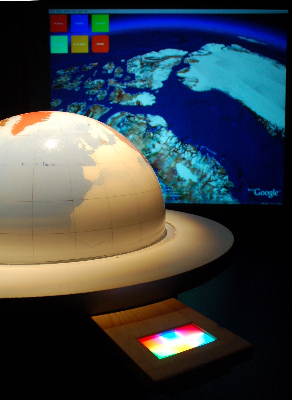
The globe is made of a cylindrical wood stand, holding an acrylic semi sphere representing the north hemisphere.
This semi sphere is painted on it’s inner surface, giving and artistic but geographically correct representation of the land and sea.
We wanted this particular exhibit to meet several goals :
– be able to choose easily a point on the physical globe, and visualize it directly in GoogleEarth(GE),
– be able to move the GE view in a different place (eventually not accessible via the physical globe) easily,
– have access to usual navigation features in GE (zoom, pan, tilt, ...)
– have access to more information via KML layers easily.
For short, the point is to use GoogleEarth without mouse, without keyboard, and whitout the burden of unfolding and selecting items in the "My Places" pane.
(for videos, check here)
Interfaces
To achieve this goal, three inputs have been created :
– "touch" point detection on the physical globe,
– view control via Wiimote,
– layer selection through a backlit touchpad, containing 6 zones, leaving 6 different possible choices to the user. Those choices can be extended by using a hierarchical organization (for instance : Climate->Ice->Permafrost).
Those interfaces drive the display in GE (moving to the chosen point, movements, layer display) thanks to a KML file loaded via a network link [1] (see "NetworkLink") and keyboard shortcuts sent to the application.
On the "outputs" side, the user gets visual feedback from GoogleEarth, projected on a screen, and from the backlit touchpad. On the lattern, each sensitive zone can be individually lit, in order to show possible choices.
All those elements are, of course, running and driven from a Linux box.
General Architecture
Early in the development process, the task start to look pretty complex.
First, each input subsystems introduces challenges.
Touchpad driving requires hardware handling to find the touched point and to handle the 6 zones lighting. The physical globe touch detection required a lot of experimentation, since it was vision based, and went through several steps (see Presentation du projet and Premiers essais de vision).
Driving the display thru KML files was also initially instable : GoogleEarth didn’t seem to react consistently when placemarks placemarks" were used, wandering around erratically.
Wiimote,driving, a pretty simple task (with libwiimote), introduced some problems : random detection, unable to resync when the Wiimote went out of range, ..
A scenario description system alos had to be developped to ease the creation and change of the displayed layer content without requiring recompiling code.
Finally, all thos elements must cooperate together to drive GoogleEarth consistently, and must start and synchronize properly.
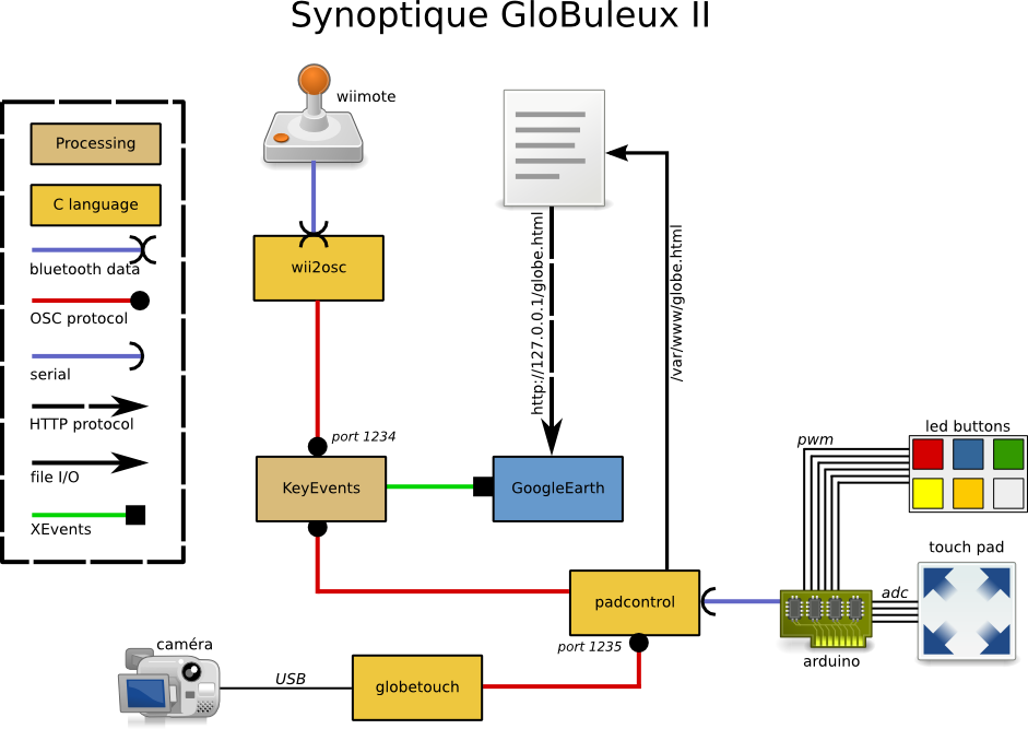
This figure show the different sub-systems created to create the final prototype. OSC (Open Sound Control), a netwok protocol mainly capable of transmitting key/value pairs, is used to connect the subsystems together.
Subsystems
GoogleEarth
On the computer hosting all the application, GoogleEarth is the final element of the link. It is configured to use a network link pointing to a local Apache daemon, serving a KML file update.kml.
GE starts last, and KeyEvents is responsible to select the network link in the "My Places" pane, and to set GE full screen.
KeyEvents
KeyEvents has been developed with Processing (some kind of Java superset). This application receives requests from other subsystems via OSC (using the great oscP5 library) and sends key events corresponding to required actions to GoogleEarth.
for instance, when the Wiimote "up" key is pressed, an OSC packet will be received by KeyEvent; KeyEvent will generate a keyboard event corresponding to the "up" key on the keyboard and send it to GE.
This application uses the Robot Java class, which is able to generate keyboard and mouse events. This method might seem poorly robust, but nothing is available to drive GoogleEarth from linux. A GE driving API exists, but as a COM API component, only under win32.
Others solutions have been triend, notable X events. But those developement were stopped short since they weren’t satisfying (Robot class uses X events too, but more reliably than we did !). Despite the first worries, the result is really stable.
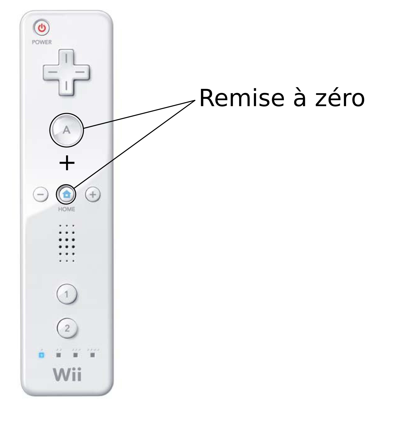
As an example, we implemented a "panic" mode : if you press "A" and "Home" keys simulteanously on the Wiimote, X windowd is restarted (and thus, all applications). To achieve this, we have to simulation a "Ctrl-Alt-Backspace" keypress.
The following code does this with a few lines :
void setup()
{
...
robot = new Robot();
...
}

void send_ctrl_alt_backspace()
{
  println("Got Ctrl-Alt-Backspace code");
  robot.keyPress(KeyEvent.VK_CONTROL);
  robot.keyPress(KeyEvent.VK_ALT);
  robot.keyPress(KeyEvent.VK_BACK_SPACE);
}
Usually, a keyRelease event must be sent after a keyPress. In this case, there is no need to do so since X (and KeyEvents itself) will be dead.
OSC packet reception is handled by a callback : this "callback" (a function) is called when a packet arrives. This function then analyses the packet content and take appropriate action.
In each received packet, the state of all Wiimote buttons is available. The follong code, taken from the callback, fills an array containing the buttons states :
void oscEvent(OscMessage theOscMessage) {
  //println("Got osc message");
  /* get and print the address pattern and the */
  /* typetag of the received OscMessage */
  if(theOscMessage.checkAddrPattern("/erasme/globe/2/wiimote/0/state")==true) {
    /* check if the typetag is the right one. */
    if(theOscMessage.checkTypetag("iiiiiiiiiii")) {
      /* parse theOscMessage and extract */
      /* the values from the osc message arguments. */
      for(int i=0; i<=ihome; i=i+1) {
        wii_states[i] = theOscMessage.get(i).intValue();
       }
....
The rest of the code will trigger appropriate events depending on the which buttons have been pressed.
KeyEvents also receives Wiimote accelerometer values in an other packet (differentiated by checkAddrPattern). KeyEvents also handles reload requests, and sends a Ctrl-R sequence to GE when received.
wii2osc
As its name says, wii2osc transforms Wiimote events in OSC packets. More specificaly,each type the Wiimote changes state (accelerometer values, key press or release), an OSC packet is sent to KeyEvents.
wii2osc uses libwiimote library, which handles the burden of bluetooth-level communication and Wiimote protocol decoding, and liblo, which is used to build and send OSC messages. This last library has been patched in order to be able to send packets to braodcast addresses [2].
libwiimotelets you discover Wii peripherals : you can then associate to any Wiimote. But we choosed to use a directed association, using specific wiimote hardware address, in order to avoid hijacking from rogue Wiimotes.
globetouch
This is the vision application in the set, in charge of detecting touch on the physical globe. The detection technique is quite simple, and is detailed in another article.
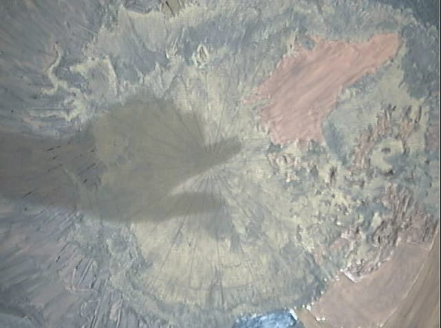
In summary, the idea is to grab the user’s hand shadow over the globe surface, and to calculate the pointing finger position. This information is then sent in an OSC packet to padcontrol (see below).
The application achieves this by "learning" a mean image, representing the background, and by comparing it to a newly acquired image. Differences tell that an object -hopefully, a hand) is in the field. The learning behaviour is permanent : any modification in the environment (sun passing behind a cloud, lamp being turned on of off, ...) will slowly be integrated to the mean background image.
globetouch is pretty picky about contrast : if the light above the globe if too weak, cast shadows won’t be detected. Moreover, the paint used to paint the globe inner side is thicker in some areas than in others, which make detection harder in some areas if contrast is not good enough.
Another part of interest in the code is coordinates transformation and camera calibration. The image grabbed by the camera sensor is flat. But the coordinates we need from the point touched on the physical globe have to be polar : latitude, longitude. So we have to convert those planar (cartesian) coordinates into polar ones.
This can only be done with perfectly calibrated camera with its positiong known : it must be centered, and its orientation and the globe radius must be known.
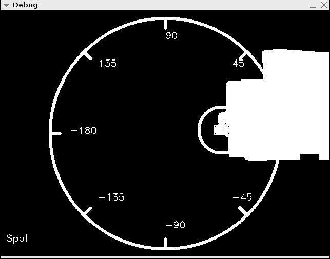
To achieve this, a reference point is touched bu the used at calibration time : this helps to determine the relative camra orientation to the Greenwich meridian so we can apply a shift to the longitudes we calculate. Similarly, the latitude of the designated point let us calculate the globe size (in pixels) as seen by the camera. With this data, we can then use the standard transformation equations to convert planar to polar :
longitude = atan(y/x);
latitude = acos(sqrt(x * x +y * y)/globe_radius);
(where x and y are the touched spot coordinates, relative to the sensor’s center).
Finaly, a problem came up rather quickly : GoogleEarth was doing spurious movements when a person was moving her hand over the globe, without touching it.
At first glance, this problem seemed rather annoying to solve : how could we know of the globe has really been touched or not ?
One of the only solutions that seemed realistic was to add a capacitive sensor to detect a touch, with all the problems that would come along : sensor driving, spiral electrode running inside the globe with side effects we could imagine, ... Nothing very appealing.
An elegant solution has finally been found by Patrick Vincent : we could just check that the detected finger stays long enough in the same position over the globe. If so, we can be sure at 99% that the finger was laying on the globe surface (if it wasn’t, it would probably move).
This solution has big advantages : no need to drive more external circuitry, and it can be handled by the existing vision software. After few hours of fine tuning the parameters (still time, movement tolerance, ...), it appeared to be very efficient.
padcontrol
padcontrol, written in C, is, along with globetouch, the biggest piece of code of the whole setup. It is very modest though, hitting barely 1000 lines. But this application is the most critical of all : it handles KML file refresh triggered by touchpad, talks to the Arduino to drive the touchpad backligh, and get feedback from the pad, receives OSC events from globetouch indicating that a point has been touched on the physical globe (generating a new KML file), and last but not least, sends OSC notifications to KeyEvents asking to send a reload to GoogleEarth in order to refresh the network link. padcontrol can also set GoogleEarth in "cache filling" mode : after a configurable inactivity time, it will generate KML files with random places (bound by a latitude/longitude configurable window). padcontrol then asks GoogleEarth to reload the network link. The GE cache will then fillup with preloaded places, accelerating subsequent loading times when the location has already been visited.
padcontrol has many datasources to check. This multiplexer behaviour implied important design decisions.
Threads were quickly choosed. First, because of liblo, the library that takes care of handing OSC packets. This library implements OSC packet handling in threaded callbacks. We also wanted to take advantage from the host PC multi-core architecture, and have a separate KML update thread, indepedant from the rest of the code.
Threads and OSC use made the whole setup very robust, despite the whole range of interfaces and applications used : if the vision part (globetouch) fails (camera failure ou software crash), the rest of the setup can still work without physical globe touch detection. The same applies to the Wiimote : event if the Arduino burns, the other functions will still work, since Arduino handling is done in a thread and therefore non-blocking for the application.
Far from being a masterpiece, padcontrol nevertheless contains several interesting things for the average programmer I am : threads, mutexes, pthread_conds, serial communications, network communications via OSC, complex configuration file reading (with libconfuse), sighandlers... All in all, a bunch of example code, reusable in many projects, mainly in the microcontroller field.
Arduino & touch pad
The hardware part is Arduino based. Even if we try to use bare microcontrollers first, Arduino is really handy when you need to communicate with a PC. Using a bare chip, you always need to convert the serial TTL levels. Not hard, but it is really annoying and time consuming to solder the usual max232 and all his caps. The Arduino library also provides handy abstractions, mainly for PWM generation and serial port, lowering design and development, and debugging time by a factor 2 at least. The downside is footprint (Arduino NC), but in our situation, room is not a problem !
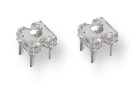
The Arduino will handle touch pad position reading and backlighting with 6 Lumiled Superflux diodes.
– LED driving
LEDs are PWM (Pulse Width Modulation) driven. This provides several light intensity values (256) between "off" and "on". Thanks to the AVR ATmega168 on the Arduino, we have 6 channels on hand, able to generate PWM. All lignthing is thus handled with PWM, going progressively from 0 to 255 over 1 second. Turning LEDs or and off is softer, less aggressive this way, and give a "pulse" effects to the lighting.
Diodes have been empirically calibrated : LEDs with main red component looked much brigther than "cold" (blue, green, cyan) ones. PWM values have been compensated to correct the visible light power difference.
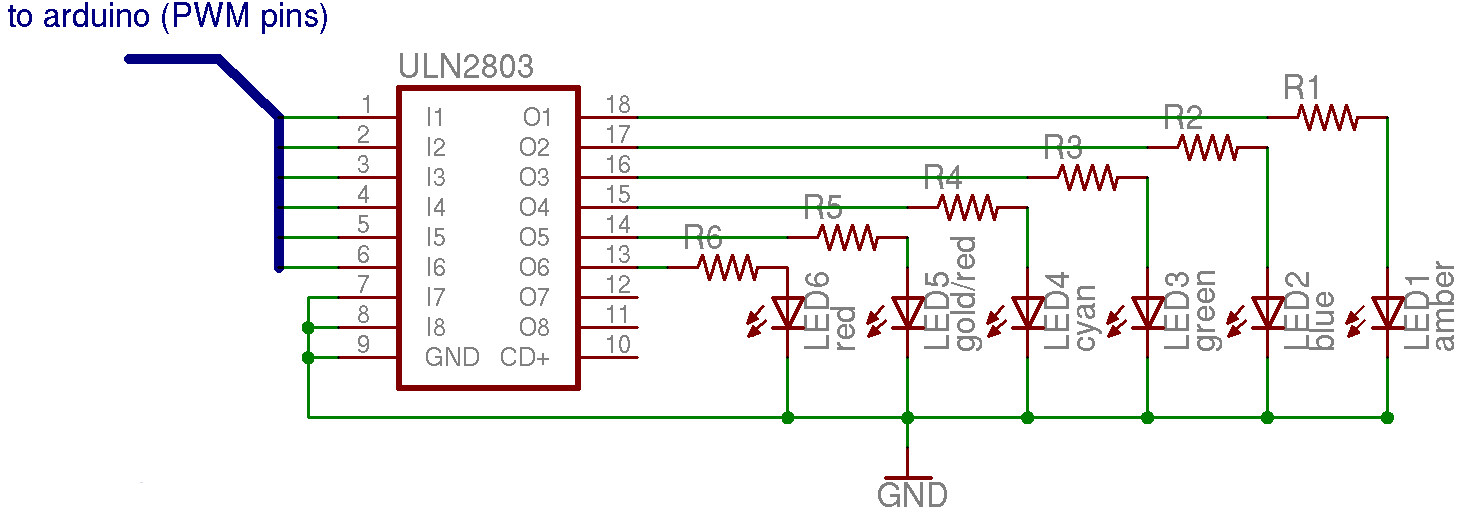

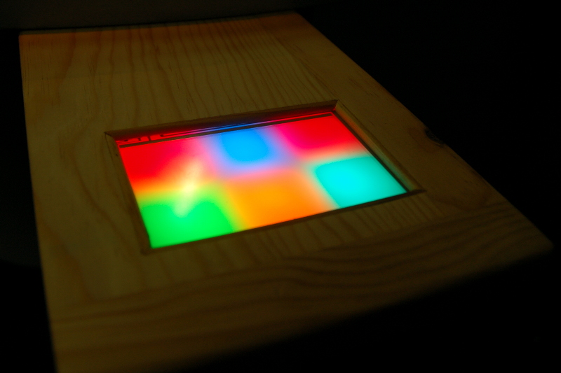
Selected LEDs (Lumileds Superflux) require between 50 et 70mA. The microcontroller being unable to supply this amount of current, a very small board, based on the excellent ULN2803 by Texas Instruments, has been created to supply the LEDs. This circuit has been built as an Arduino shield, to ease integration. A HE-10 flat cable brings the power to the LED module. Those LEDs are located behind a white acrylic diffuser to give a fuzzy effect, and remove the LED visual hot spot.
– Touchpad handling
The touchpad, sold by Sparkfun, is a 4-wire resistive type. Those wires are connected to two conductive layers (ITO) separated by an insulator. When pressure is applied to the pad, conductive layers touch each other, creating a voltage divisor (layers have a resistance between 500 et 700 Ohms approximately). Speaking about Sparkfun, I take this opportunity to thank them for their great catalog and excellent and ultra-fast customer relashionship. Many of our projects use Sparkfun’s hardware. Thanks a lot. You guys rock !
There are two wires per axis (X+, X- for horizontal axis, Y+, Y- for vertical axis).
Thus, to mesure and locate a contact point, we will use the following method :
1- apply 5v to X+
2- apply 0v to X-
3- read voltage on Y+ (or Y-, it doesn’t matter) with an ADC
If voltage read if, for instance, 2.5v, it means that the finger is at the center of the screen. The higher the voltage, the closer the finger is to X+. The lower the voltage, the closer the finger is to X-.
To read the position (voltage) on the Y axis, we’ll do the same operation inverting the electrodes (Y+ at 5v, Y- at 0v, ADC read on X+).
So in order to get a position (a result on both axes), we need two measurements.
With the ADC doing 10bits conversions, we have 2^10 possible values (1024). This means we’ll have a 1024x1024 resolution on the screen. Given the screen size, this is much more than needed.
The result will be splitted the check wich of the 6 zones the user pressed.
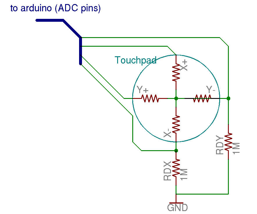
The touchpad is driven directly by the Arduino. We just have to add to pull-down resistors, in order to be able to read 0v when no touch is made on the pad. Without this pull-down resistor, the voltage read on the electrode is floating, and values are invalid for our application. The resistor values must be as high as possible (but not too much too, to avoid side-effects). They are taken in account in the voltage divisor when a touch is made (RDY with Y- for X+ at 5v and X- at 0v for instance) ! Choosing high values will minimize they impact on the measurements.
Arduino is sending the values read upon request. So it’s the padcontrol job to drive indirectly the acuisition. padcontrol will compute which zone has been touched from the values read y the ADC, and compare them to the values read in it’s configuration file :
...
/* Buttons zones */
button 0 {
        /* N, S, W, E limits */
        limits = { 131, 469, 70, 358 }
}

button 1 {
        /* N, S, W, E limits */
        limits = { 131, 469, 359, 647 }
}

button 2 {
        /* N, S, W, E limits */
        limits = { 131, 469, 648, 937 }
}
button 3 {
...
those three buttons are found on the upper part of the touchpad. You can see some values are excluded (y values below 131, x values below 70, ...). Those ranges are not usable given physical constraints (i.e. you won’t ever read 0 or 5 volts from the screen, since these is some unusable margin). This reduces resolution, but it still fine for our application.
– Integration
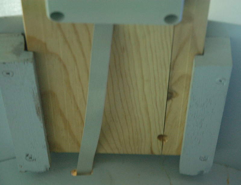
LEDs, light diffuser and touchpad are sandwiched in a woodent frame. Vertical spacers separate LEDs from the diffuser. Almost all the electronic (beside LEDs and associated resistors) is located inside the globe, and connected via a HE-10 flat cable. This minimize the possibility for the user to fiddle with the hardwar (especially usefull with kids :).
Scenarios
Defined scenarios are organized in a tree-like fashion, so the user can navigate the different layers displayed in GE. For each pad selection, GE diaplay and touchpad lighting are refreshed to reflect selection and available submenus (if any).
Scenario specification is set in the padcontrol configuration file :
scenario Root {
         path = { 0 }
         kml    = "0.kml"
}

scenario Populations {
         path = { 0, 0 }
         kml    = "00.kml"
}

scenario Regions {
         path = { 0, 1 }
         kml    = "01.kml"
}
scenario Territories {
         path = { 0, 2 }
         kml    = "02.kml"
}

scenario Nuvavut {
         path = { 0, 2, 0 }
         kml    = "020.kml"
}
scenario Nuvaviq {
         path = { 0, 2, 1 }
         kml    = "021.kml"
}
scenario Quit025 {
         path = { 0, 2, 5 }
         is_quit = 1
}
...
In this configuration example, GE starts with the "Root" scenarii, and padcontrol updates the GE Network Link to make it point to the 0.kml file. At this time, the pad lights are off. A touch on the pad lights it up and mae the menu appear. On ly buttons 1 and 2 on the pad are lit (these are the only submenus available). If the user then presses the #2 button, the 02.kml file will be loaded by GE, and three submenus will then be available (0, 1 and 5).
If the user selects 1, a new KML file will be loaded adding a layer representing Nunaviq territory. If she selects 5 instead, she will be taken back to the normal display.
This system is very easy, and let’s the developper to quickly change the scenario. Il also let the developper to take advantage of the KML rich features (bitmap display, live layers for Internet, ...), since only KML is used.
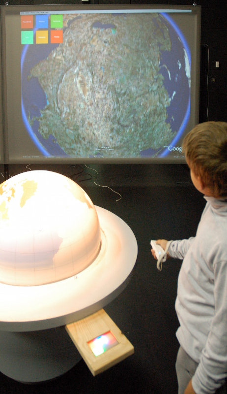
Conclusion
This interactive installation adds tangible interfaces to GE without adding any mouse or keyboard. the globe has been used in an exhibit situation at the ’Barthelemy Thimonnier’ museum in Amplepuis, France, and helped visitors, alone or chaperoned, to discover polar territories in a completely new way.
Even if this project mught be hard to reproduce elsewere (not everybody has a 1 meter half sphere of acrylic representing earth in it’s garage), some parts of the design are easily usable in other projects. Specifically, wii2osc and KeyEvents tools are sufficient, for instance, in a classroom, to use GE with a Wiimote, and discover the planet.
Code
All the produced code is GPLv2. Since some cleaning is required for publication, and since we don’t really have enough time for that, it is not published. However, feel free to as us for it if you need it.
Thanks
Many thanks to all the folks who were involved one way or another in the development process : Pierre-Gilles, Daniel, Patrick, Christophe, Laetitia, Catherine.
Many thanks also to the beta testers (ERASME folks & kids).
Links
G2 : Primer on the interactive globe project (fr)
G2 : Firsts vision tests for the globe (fr) interactif
GloBuleux 2 : an interactive globe in Inuit territories (fr)